Set Pressure
How to define the correct set pressure?
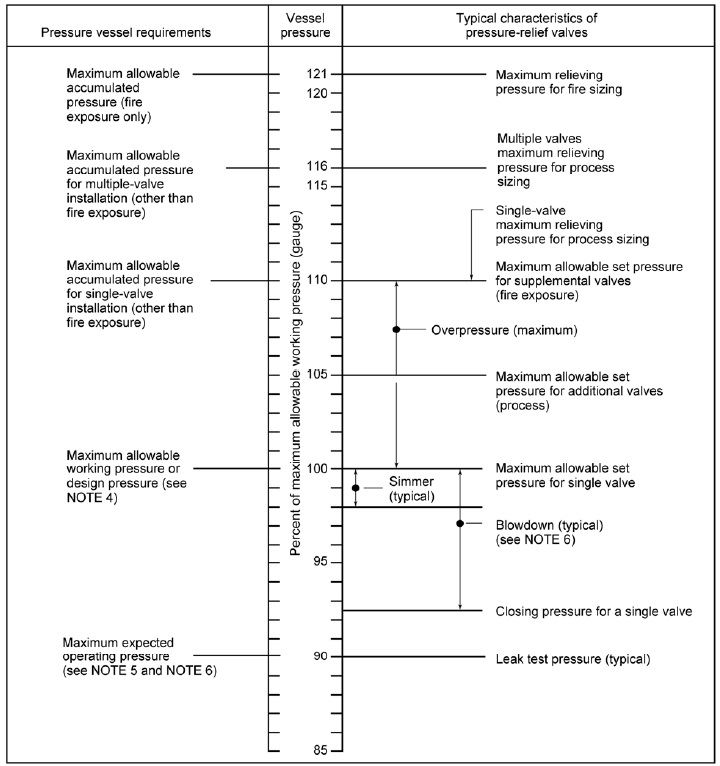
To determine the correct set pressure for a safety valve, several key terms and factors must be carefully evaluated:
- Set Pressure (Pset): It is the initial audible leaking pressure value.
- Relieving Pressure (POP): It's the pressure at which the safety valve achieves its full capacity. It's calculated as the sum of the set pressure (PSet) and the overpressure (PO).
- Overpressure (PO): This is the percentage of the set pressure at which the safety valve is designed to operate. According to the most relevant standard like ISO4126, ASME VIII, ASME XIII and API520 this value is usually set at 10% of set pressure or +0,1barg whichever is greater.
- Maximum Allowable Working Pressure (MAWP): Also known as the safe working pressure (SWP) or design pressure, this is the maximum pressure the system can handle under normal operating conditions, considering the maximum operating temperature.
- Maximum Allowable Accumulation Pressure (MAAP): This represents the maximum pressure allowed in the system as per the design standards. It's often expressed as a percentage of the MAWP, with typical values being 10% higher than the MAWP for pressure systems. However, this may vary, and it's essential to consult the relevant authority if the MAWP is not readily available.
- Normal Working Pressure (NWP): This is the operating pressure of the system under full-load conditions.
When defining the set pressure for a safety valve, two critical concepts must be considered:
- The set pressure should be low enough to ensure that the relieving pressure never exceeds the Maximum Allowable Accumulation Pressure (MAAP) of the system.
- The set pressure should be high enough to provide sufficient margin above the Normal Working Pressure (NWP) for the safety valve to close. However, it must never exceed the Maximum Allowable Working Pressure (MAWP).
By understanding and appropriately considering these terms and constraints, the set pressure for a safety valve can be determined accurately, ensuring optimal performance and system safety.
Setting a safety valve
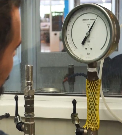
To establish the certified initial audible leaking pressure of a safety valve, a test bench is essential. The operator begins by installing the Pressure Safety Valve (PSV) and a pressure gauge on the test bench. It's imperative to use a certified pressure gauge to ensure accurate determination of the set pressure value. The pressure gauge should be of at least class 0.6, meeting strict calibration standards for precision and reliability. In the case of an analogic gauge, it's crucial that the set pressure value falls within two-thirds of the gauge's dial range. This ensures proper alignment between the gauge's measurement capabilities and the desired set pressure, facilitating accurate calibration of the safety valve.
The operator will gradually increase the pressure until they detect the audible leakage from the valve. It's important to note that using a detector is prohibited, as it may result in detecting the leakage value as per API 527, rather than the set pressure value. The set pressure verification process must be repeated at least three times, with the pressure incrementally raised and then dropped to zero each time. The third reading obtained represents the official set pressure value. This method is particularly crucial when dealing with soft seals, as there is a possibility that the elastomer may adhere to the safety valve nozzle.
The set pressure tolerance is outlined in various standards such as ASME XIII, ASME VIII Div.1, ISO 4126, and API 520. According to these standards, the set pressure must fall within a tolerance of 3% or +/- 0.1 barg, whichever value is greater.
Sealing
For valves without specific standards or references, there are no restrictions on who can set them. Typically, these valves serve to indicate pressure levels rather than act as safety devices.
However, for valves independently approved by a notified body to a specific standard, setting and sealing procedures are integral to the approval process. In such cases, only the manufacturer or an approved laboratory following designated quality protocols and using authorized equipment can adjust the valve.
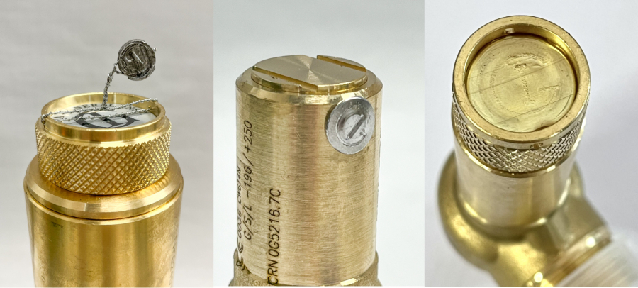
Additionally, most standards mandate sealing provisions, commonly achieved by using sealing wire, rivet or caps to secure the cap to the spring housing and the housing to the body.
Worried about the maintenance of a safety valve? Click here!
Leak Test and Set Pressure
Leak test and set pressure are related but distinct concepts in the context of safety valves used in various industries.
Set Pressure
Set pressure is defined in the UNI EN1097:2023 standard as the initial pressure at which the leak of a safety valve becomes audible. This definition implies that determining this value requires the use of human hearing or a mechanical ear, such as a certified microphone, capable of perceiving the same sound intensity and frequency as a human ear. Instruments like testers, sniffers, leak detectors, or other devices designed to detect fluid leaks cannot be used for evaluating the set pressure of safety valves.
Leak Test - Definition
The leak test according to API 527, as defined by the American Petroleum Institute (API), is designed to assess a safety valve's ability to maintain a tight seal when closed, simulating normal operating conditions.
Leak Test - Configuration
This test can be conducted using various methodologies, with the most common involving air as the test fluid at ambient temperature. Leakage is measured as the number of bubbles in water using a tube with an outer diameter of 7.9 mm (5/16 inches) and a wall thickness of 0.89 mm (0.035 inches). The tube end should be cut square and smooth, with the tube opening 12.7 mm (1/2 inch) below the water surface. The tube should be perpendicular to the water surface.
Leak Test – Test Pressure
For a safety valve with a set pressure greater than 3.45 barg (50 psig), the bubble leakage rate must be determined with the test pressure at the valve inlet maintained at 90% of the set pressure. For a valve set at 3.45 barg (50 psig) or lower, the test pressure should be held at 0.35 bar (5 psi) below the set pressure.
Leak Test – Acceptance Criteria
During the one-minute duration of the leak test, a soft-seated safety valve should exhibit no leakage (0 bubbles/min). For a metal-to-metal seated safety valve, the bubble leak rate should not exceed the values specified in the table below.
| Set Pressure Pset |
Orifice equal or smaller than 18mm Max Leak Allowed |
Orifice larger than 18mm Max Leak Allowed |
|---|---|---|
| From 1 barg to 69 barg | 40 bolle/min | 20 bolle/min |
| 103 barg | 60 bolle/min | 30 bolle/min |
| 138 barg | 80 bolle/min | 40 bolle/min |
| 172 barg | 100 bolle/min | 50 bolle/min |
| 207 barg | 100 bolle/min | 60 bolle/min |
| 276 barg | 100 bolle/min | 80 bolle/min |
| 345 barg | 100 bolle/min | 100 bolle/min |
| 414 barg | 100 bolle/min | 100 bolle/min |
Alternative Leak Test
Alternative methods for safety valve leak tests are permitted, provided they are recognized and certified by regulatory bodies as more accurate. Nuova General Instruments has obtained approval from the official notified body, ASME National Board, to utilize leak verification as a seal test method. This verification is conducted using a nitrogen and hydrogen mixture (95% N2 - 5% H2), with pressure sets compliant with API 527. A positive test result is confirmed only in the absence of leaks detected by the certified leak detector, with a sensitivity of 1 x 10⁻⁵ cc/s.